Section Introduction:
In the previous section, we learned about Xfermode's two sons who have already passed away (become obsolete):AvoidXfermode, PixelXorXfermode, although they are somewhat useful, they are ultimately obsolete. In this section, let's learn about Xfermode's third son, who is still alive:PorterDuffXfermode;
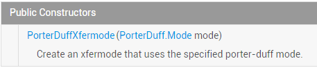
First, let's present the official API documentation:PorterDuffXfermode! The documentation content is very limited; we can see its constructor:
There is only one parameter:PorterDuff.Modemode, and Android provides us with 16 image blending modes. Simply put, two layers can be combined according to different modes to produce different results! The result diagrams of the 16 blending modes are as follows:
Here are the two layers: the image drawn first isdestination image (DST), and the image drawn later issource image (SRC)!
Of course, in the documentation we find that the available modes are not 16 but 18, with the addition ofADDandOVERLAYtwo modes!
Well, talking more is useless; code is the most practical. In this section, let's write code to verify these 18 modes!
PS: The name PorterDuff is actually a combination of two people's names: Tomas Proter and Tom Duff. They were the great masters who first proposed the concept of graphical blending at SIGGRAPH. If you are interested, search on Baidu yourself~
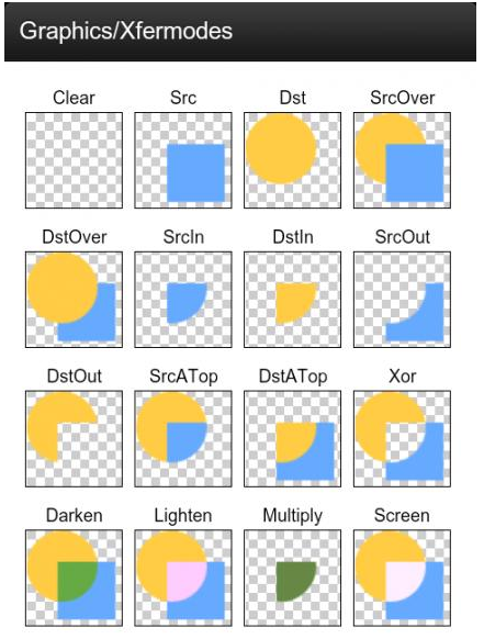

Let's write an example to verify the above diagram:
Alright, let's write an example to verify the above diagram, and compare and analyze the results by switching between different modes!
Code Implementation:
Step 1: First, let's write a utility class to get the screen width and height!ScreenUtil.java:
/**
 * Created by Jay on 2015/10/23 0023.
 */
public class ScreenUtil {
    /**
     * 获取屏幕宽高,sdk17后不建议采用
     *
     * @param context
     */
    public static int[] getScreenHW(Context context) {
        WindowManager manager = (WindowManager) context.getSystemService(Context.WINDOW_SERVICE);
        Display display = manager.getDefaultDisplay();
        int width = display.getWidth();
        int height = display.getHeight();
        int[] HW = new int[] { width, height };
        return HW;
    }

    /**
     * 获取屏幕宽高,建议采用
     *
     * @param context
     */
    public static int[] getScreenHW2(Context context) {
        WindowManager manager = (WindowManager) context.getSystemService(Context.WINDOW_SERVICE);
        DisplayMetrics dm = new DisplayMetrics();
        manager.getDefaultDisplay().getMetrics(dm);
        int width = dm.widthPixels;
        int height = dm.heightPixels;
        int[] HW = new int[] { width, height };
        return HW;
    }

    /**
     * 获取屏幕的宽度
     *
     * @param context
     * @return
     */
    public static int getScreenW(Context context) {
        return getScreenHW2(context)[0];
    }

    /**
     * 获取屏幕的高度
     *
     * @param context
     * @return
     */
    public static int getScreenH(Context context) {
        return getScreenHW2(context)[1];
    }
}
Step 2: Write our custom View class and do experiments here!XfermodeView.java:
/**
 * Created by Jay on 2015/10/23 0023.
 */
public class XfermodeView extends View {

    private PorterDuffXfermode pdXfermode;   //定义PorterDuffXfermode变量
    //定义MODE常量,等下直接改这里即可进行测试
    private static PorterDuff.Mode PD_MODE = PorterDuff.Mode.ADD;
    private int screenW, screenH; //屏幕宽高
    private int width = 200;      //绘制的图片宽高
    private int height = 200;
    private Bitmap srcBitmap, dstBitmap;     //上层SRC的Bitmap和下层Dst的Bitmap

    public XfermodeView(Context context) {
        this(context, null);
    }

    public XfermodeView(Context context, AttributeSet attrs) {
        super(context, attrs);
        screenW = ScreenUtil.getScreenW(context);
        screenH = ScreenUtil.getScreenH(context);
        //创建一个PorterDuffXfermode对象
        pdXfermode = new PorterDuffXfermode(PD_MODE);
        //实例化两个Bitmap
        srcBitmap = makeSrc(width, height);
        dstBitmap = makeDst(width, height);
    }

    public XfermodeView(Context context, AttributeSet attrs, int defStyleAttr) {
        super(context, attrs, defStyleAttr);
    }


    //定义一个绘制圆形Bitmap的方法
    private Bitmap makeDst(int w, int h) {
        Bitmap bm = Bitmap.createBitmap(w, h, Bitmap.Config.ARGB_8888);
        Canvas c = new Canvas(bm);
        Paint p = new Paint(Paint.ANTI_ALIAS_FLAG);
        p.setColor(0xFF26AAD1);
        c.drawOval(new RectF(0, 0, w * 3 / 4, h * 3 / 4), p);
        return bm;
    }

    //定义一个绘制矩形的Bitmap的方法
    private Bitmap makeSrc(int w, int h) {
        Bitmap bm = Bitmap.createBitmap(w, h, Bitmap.Config.ARGB_8888);
        Canvas c = new Canvas(bm);
        Paint p = new Paint(Paint.ANTI_ALIAS_FLAG);
        p.setColor(0xFFFFCE43);
        c.drawRect(w / 3, h / 3, w * 19 / 20, h * 19 / 20, p);
        return bm;
    }

    @Override
    protected void onDraw(Canvas canvas) {
        Paint paint = new Paint();
        paint.setFilterBitmap(false);
        paint.setStyle(Paint.Style.FILL);
        canvas.drawBitmap(srcBitmap, (screenW / 3 - width) / 2, (screenH / 2 - height) / 2, paint);
        canvas.drawBitmap(dstBitmap, (screenW / 3 - width) / 2 + screenW / 3, (screenH / 2 - height) / 2, paint);

        //创建一个图层,在图层上演示图形混合后的效果
        int sc = canvas.saveLayer(0, 0, screenW, screenH, null, Canvas.MATRIX_SAVE_FLAG |
                Canvas.CLIP_SAVE_FLAG |
                Canvas.HAS_ALPHA_LAYER_SAVE_FLAG |
                Canvas.FULL_COLOR_LAYER_SAVE_FLAG |
                Canvas.CLIP_TO_LAYER_SAVE_FLAG);

        canvas.drawBitmap(dstBitmap, (screenW / 3 - width) / 2 + screenW / 3 * 2,
                (screenH / 2 - height) / 2, paint);     //绘制i
        //设置Paint的Xfermode
        paint.setXfermode(pdXfermode);
        canvas.drawBitmap(srcBitmap, (screenW / 3 - width) / 2 + screenW / 3 * 2,
                (screenH / 2 - height) / 2, paint);
        paint.setXfermode(null);
        // 还原画布
        canvas.restoreToCount(sc);
    }
}
The code looks complicated, right? Actually it's not. It just gets the screen width and height, then draws a rectangle and a circle, calculates their positions, sets the layer (a fixed pattern), then sets the paint's setXfermode, and then draws to the canvas. What you might not understand is the calculation of drawing positions, but that's not the case - you can set the positions however you like! Next, let's check the results one by one. You just need to changePD_MODEthe value to different modes!
Running effect screenshots:
1)PorterDuff.Mode.ADD:
 Saturation overlay
2)PorterDuff.Mode.CLEAR:
 The drawn content will not be committed to the canvas. Well, the result... I don't know why, normally there is nothing...
3)PorterDuff.Mode.DARKEN:
 Take the entire area of both layers, and darken the color of the intersection part
4)PorterDuff.Mode.DST:
 Only the alpha and color of the target image are retained, so only the target image is drawn
5)PorterDuff.Mode.DST_ATOP:
 Draw the target image where the source and target images intersect, and draw the source image where they do not intersect
6)PorterDuff.Mode.DST_IN:
 Draw the target image where the two intersect, and the drawing effect is affected by the transparency of the original image
7)PorterDuff.Mode.DST_OUT:
 Draw the target image where they do not intersect
8)PorterDuff.Mode.DST_OVER:
 The target image is drawn on top
9)PorterDuff.Mode.LIGHTEN:
 Take the entire area of both layers, and lighten the color of the intersection part
10)PorterDuff.Mode.MULTIPLY:
 Take the overlaid color of the intersection part of the two layers
11)PorterDuff.Mode.OVERLAY:
 Overlay
12)PorterDuff.Mode.SCREEN:
 Take the entire area of both layers, and the intersection part becomes transparent
13)PorterDuff.Mode.SRC:
 Only the alpha and color of the source image are retained, so only the source image is drawn
14)PorterDuff.Mode.SRC_ATOP:
 Draw the source image where the source and target images intersect, and draw the target image where they do not intersect
15)PorterDuff.Mode.SRC_IN:
 Draw the source image where the two intersect
16)PorterDuff.Mode.SRC_OUT:
 Draw the source image where they do not intersect
17)PorterDuff.Mode.SRC_OVER:
 Draw the source image on top
18)PorterDuff.Mode.XOR:
 Where they do not intersect, draw the source and target images as they are
Download the sample code for this section:
PorterDuffXfermodeDemo.zip
Section Summary:
Well, in this section, we just wrote a simple View to verify the different effects under these 18 different PorterDuff.Mode values. Hehe, it took quite a while, but it must be much clearer for readers, right? Of course, these are just some preliminary insights!
PorterDuffXfermodeofPorterDuff.ModeIt is very important for our custom controls! In this section, we got a preliminary understanding. In the next section, let's pick a few examples to practice!
If you want to see a more detailed introduction to PorterDuff.Mode, see:Android Paint: Explanation of setXfermode PorterDuffXfermode, a well-written article by someone else! Well, that's all for now. I have a medical check-up tomorrow morning, so that's all I wrote today~
