Keywords: Delay, Inertial Delay
The delay in the continuous assignment delay statement is used to control the time delay from when any operand changes to when the left side of the statement is assigned a new value.
Delays are generally not synthesizable.
Register delays can also be controlled; this is explained in the timing control section.
Continuous assignment delays can generally be divided into ordinary assignment delay, implicit delay, and declaration delay.
The following 3 examples are functionally equivalent, corresponding to three different ways of writing continuous assignment delays.
wire Z, A, B ;
assign #10 Z = A & B ;
//Implicit delay, when declaring a wire variable, perform a continuous assignment to it with a certain delay.
wire A, B;
wire #10 Z = A & B;
//Declaration delay, when declaring a wire variable, a delay is specified. Therefore, all continuous assignments to this variable will be deferred to the specified time. Unless in gate-level modeling, this method of modeling is generally not recommended.
wire A, B;
wire #10 Z ;
assign Z =A & B
Inertial Delay
In the above example, if either A or B changes, there will be a 10 time unit delay before Z gets a new value. If within these 10 time units, i.e., before Z obtains a new value, either A or B changes again, then the current new value of A or B will be used when calculating the new value of Z. Therefore, it is called inertial delay, meaning that if the signal pulse width is smaller than the delay, it has no effect on the output.
Therefore, during simulation, the delay must be set reasonably to prevent certain signals from being unable to be effectively delayed.
Perform a delay simulation on an AND gate logic with delay.
Example
input ai, bi,
output so_lose, so_get, so_normal);
assign #20 so_lose = ai & bi ;
assign #5 so_get = ai & bi ;
assign so_normal = ai & bi ;
endmodule
The testbench reference is as follows:
Example
module test ;
reg ai, bi ;
wire so_lose, so_get, so_normal ;
initial begin
ai = 0 ;
#25 ; ai = 1 ;
#35 ; ai = 0 ; //60ns
#40 ; ai = 1 ; //100ns
#10 ; ai = 0 ; //110ns
end
initial begin
bi = 1 ;
#70 ; bi = 0 ;
#20 ; bi = 1 ;
end
time_delay_module u_wire_delay(
.ai (ai),
.bi (bi),
.so_lose (so_lose),
.so_get (so_get),
.so_normal (so_normal));
initial begin
forever begin
#100;
//$display("---gyc---%d", $time);
if ($time >= 1000) begin
$finish ;
end
end
end
endmodule
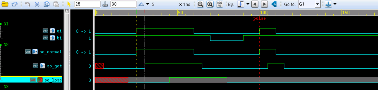
The simulation results are as follows:
The signal so_normal is normal AND logic.
Since all delays are greater than 5ns, the result of signal so_get is the AND operation delayed by 5ns.
The first part of signal so_lose is the result of the AND operation delayed by 20ns.
Since the second high-level duration of signal ai is less than 20ns, the so_lose signal will miss the delay detection of this pulse due to inertial delay, so the latter part of the so_lose signal is still 0.
Source Code Download
Download