Keywords: instantiation, generate, full adder, hierarchical access
Referencing another module within a module and connecting its ports is called module instantiation. Module instantiation establishes the hierarchy of the description. Signal ports can be associated by position or by name, and port connections must also follow certain rules.
Named port connection
This method connects the ports of the module to be instantiated with external signals by name. The port order is arbitrary and may differ from the declared port order of the referenced module, as long as the port names match the external signals.
The following is an example of instantiating a 1-bit full adder:
Example
.Ai (a[0]),
.Bi (b[0]),
.Ci (c==1'b1 ? 1'b0 : 1'b1),
.So (so_bit0),
.Co (co_temp[0]));
If some output ports do not need to be connected externally, they can be left floating or even omitted during instantiation. In general, input ports cannot be omitted during instantiation, otherwise a compilation error will occur, while output ports can be omitted during instantiation. For example:
Example
full_adder1 u_adder0(
.Ai (a[0]),
.Bi (b[0]),
.Ci (c==1'b1 ? 1'b0 : 1'b1),
.So (so_bit0),
.Co ());
//output port Co omitted
full_adder1 u_adder0(
.Ai (a[0]),
.Bi (b[0]),
.Ci (c==1'b1 ? 1'b0 : 1'b1),
.So (so_bit0));
Ordered port connection
This method matches and connects the ports of the module to be instantiated with external signals according to the port order declared in the module, and the positions must be strictly consistent. For example, the code for instantiating a 1-bit full adder can be changed to:
full_adder1  u_adder1(
    a[1], b[1], co_temp[0], so_bit1, co_temp[1]);
Although this code may take up relatively less space in writing, code readability is reduced and debugging becomes more difficult. Sometimes in large designs there may be many ports, and the order of port signals may change from time to time. In such cases, using ordered port connection for module instantiation is obviously inconvenient. Therefore, in normal practice, it is recommended to use named port connection for module instantiation.
Port connection rules
Input port
When instantiating a module, from outside the module, input ports can be connected to wire or reg type variables. This is different from module declaration; from inside the module, input ports must be wire type variables.
Output port
When instantiating a module, from outside the module, output ports must be connected to wire type variables. This is different from module declaration; from inside the module, output ports can be wire or reg type variables.
Inout port
When instantiating a module, from outside the module, inout ports must be connected to wire type variables. This is the same as module declaration.
Floating port
When instantiating a module, if certain signals do not need to be connected or interact with external signals, we can leave them floating, that is, leave the port instantiation position blank, as mentioned in the examples above.
When an output port is left floating, we can even omit it during instantiation.
When an input port is left floating, the logic function of the floating signal appears as a high-impedance state (logic value z). However, a floating input port generally cannot be omitted during instantiation, otherwise a compilation error will occur. For example:
Example
full_adder4 u_adder4(
.a (a),
.b (b),
.c (),
.so (so),
.co (co));
Example
full_adder4 u_adder4(
.a (a),
.b (b),
.so (so),
.co (co));
In general, it is recommended not to leave input ports floating; when there is no other external connection, assign them a constant value. For example:
Example
.a (a),
.b (b),
.c (1'b0),
.so (so),
.co (co));
Bit-width matching
When the bit width of an instantiation port does not match that of the continuous signal, the port will be matched by right-aligning or truncating the unsigned number.
Suppose in module full_adder4, ports a and b both have a bit width of 4 bits. The instantiation result of the following code will cause:u_adder4.a = {2'bzz, a[1:0]}, u_adder4.b = b[3:0] 。
Example
.a (a[1:0]), //input a[3:0]
.b (b[5:0]), //input b[3:0]
.c (1'b0),
.so (so),
.co (co));
Port continuous signal types
The signal types connected to ports can be: 1) identifiers, 2) bit selects, 3) part selects, 4) concatenations of the above types, 5) expressions used for input ports.
Of course, signal names can be the same as port names, but their meanings are different; they respectively represent signals within 2 different modules.
Using generate for module instantiation
When instantiating multiple identical modules, manually instantiating them one by one is cumbersome. Using generate statements to repeatedly instantiate multiple modules can greatly simplify the programming process.
The code to repeatedly instantiate four 1-bit full adders to form a 4-bit full adder is as follows:
Example
input [3:0] a , //adder1
input [3:0] b , //adder2
input c , //input carry bit
output [3:0] so , //adding result
output co //output carry bit
);
wire [3:0] co_temp ;
//The first instantiated module generally has a different format and needs to be instantiated separately
full_adder1 u_adder0(
.Ai (a[0]),
.Bi (b[0]),
.Ci (c==1'b1 ? 1'b1 : 1'b0),
.So (so[0]),
.Co (co_temp[0]));
genvar i ;
generate
for(i=1; i<=3; i=i+1) begin: adder_gen
full_adder1 u_adder(
.Ai (a[i]),
.Bi (b[i]),
.Ci (co_temp[i-1]), //The overflow of the previous full adder is the carry-in of the next one
.So (so[i]),
.Co (co_temp[i]));
end
endgenerate
assign co = co_temp[3] ;
endmodule
The testbench is as follows:
Example
module test ;
reg [3:0] a ;
reg [3:0] b ;
//reg c ;
wire [3:0] so ;
wire co ;
//Simple drive
initial begin
a = 4'd5 ;
b = 4'd2 ;
#10 ;
a = 4'd10 ;
b = 4'd8 ;
end
full_adder4 u_adder4(
.a (a),
.b (b),
.c (1'b0), //Ports can be connected to constants
.so (so),
.co (co));
initial begin
forever begin
#100;
if ($time >= 1000) $finish ;
end
end
endmodule // test
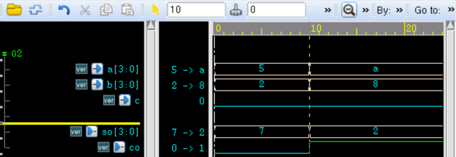
The simulation results are as follows. It can be seen that the 4-bit full adder works correctly:
Hierarchical access
The name of each instantiated module, the signal variables of each module, etc., are all defined using specific identifiers. In the entire hierarchical design, each identifier has a unique position and name.
In Verilog, by using a series of.symbols to hierarchically separate and connect the identifiers of each module, identifiers in the entire design can be accessed anywhere by specifying the complete hierarchical name.
Hierarchical access is most commonly seen in simulation.
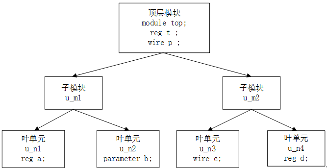
For example, with the following hierarchical design, signals among leaf cells, submodules, and the top-level module can access each other.
Example
a = top.u_m2.u_n3.c ;
//Accessing top module signals in u_n1 module
if (top.p == 'b0) a = 1'b1 ;
//Accessing u_n4 module signals in top module
assign p = top.u_m2.u_n4.d ;
In the simulations in previous sections, hierarchical access has been performed to some extent. For example"Procedural Continuous Assignment"section, the following statements were used in the top-level simulation stimulus test module:
wait (test.u_counter.cnt_temp == 4'd4) ;
Source code download
Download