Keywords: assign, full adder
Continuous assignment statements are basic statements in Verilog dataflow modeling, used to assign values to wire variables:
The format is as follows
assign LHS_target = RHS_expression ;
LHS (left hand side) refers to the left side of the assignment operation, and RHS (right hand side) refers to the right side of the assignment operation.
assign is a keyword. Any continuous assignment statement for an already declared wire variable starts with assign, for example:
wire      Cout, A, B ;
assign    Cout  = A & B ;     //实现计算A与B的功能
It should be noted that:
- LHS_target must be a scalar or a wire vector, and cannot be a register type.
- There is no requirement for the type of RHS_expression; it can be a scalar, a wire vector, or a register vector, or a function call.
- Whenever an event occurs (a change in value) on an operand of the RHS_expression, RHS_expression is immediately recalculated and assigned to LHS_target.
Verilog also provides another simple method for assigning to wire type variables, that is, assigning a value at the same time as the wire type variable is declared. A wire type variable can only be assigned once, so this kind of continuous assignment can also only be done once. For example, the following assignment method and the assignment examples above have the same effect.
wire      A, B ;
wire      Cout = A & B ;
Full Adder
In the following, a dataflow description method is used to design a 1-bit full adder.
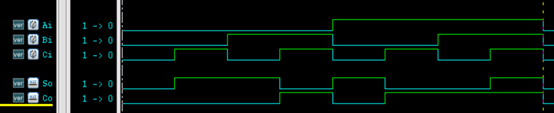
Let Ai, Bi, and Ci be the augend, addend, and carry from the adjacent lower bit, respectively; So and Co are the sum of the current bit and the carry to the adjacent higher bit, respectively.
The truth table is as follows:
| Input | Output | |||
|---|---|---|---|---|
| Ci | Ai | Bi | So | Co |
| 0 | 0 | 0 | 0 | 0 |
| 0 | 0 | 1 | 1 | 0 |
| 0 | 1 | 0 | 1 | 0 |
| 0 | 1 | 1 | 0 | 1 |
| 1 | 0 | 0 | 1 | 0 |
| 1 | 0 | 1 | 0 | 1 |
| 1 | 1 | 0 | 0 | 1 |
| 1 | 1 | 1 | 1 | 1 |
The expression of the full adder is:
So = Ai ⊕ Bi ⊕ Ci ;
Co = AiBi + Ci(Ai+Bi)
The RTL code (full_adder1.v) is as follows:
Example
input Ai, Bi, Ci,
output So, Co);
assign So = Ai ^ Bi ^ Ci ;
assign Co = (Ai & Bi) | (Ci & (Ai | Bi));
endmodule
Of course, a code description closer to an actual adder can be:
Example
input Ai, Bi, Ci
output So, Co);
assign {Co, So} = Ai + Bi + Ci ;
endmodule
The testbench (test.sv) is provided as follows:
Example
module test ;
reg Ai, Bi, Ci ;
wire So, Co ;
initial begin
{Ai, Bi, Ci} = 3'b0;
forever begin
#10 ;
{Ai, Bi, Ci} = {Ai, Bi, Ci} + 1'b1;
end
end
full_adder1 u_adder(
.Ai (Ai),
.Bi (Bi),
.Ci (Ci),
.So (So),
.Co (Co));
initial begin
forever begin
#100;
//$display("---gyc---%d", $time);
if ($time >= 1000) begin
$finish ;
end
end
end
endmodule
The simulation results are as follows:
Source Code Download
Download