Keywords: state machine, vending machine
Finite-State Machine (FSM), referred to as state machine, is a mathematical model that represents a finite number of states and the behaviors such as transitions and actions between these states. The state machine is not only a circuit description tool, but also a way of thinking, and is widely used at the system level and RTL level in circuit design.
State Machine Types
In Verilog, state machines are mainly used in the design of synchronous sequential logic, and can switch the states of sequential circuits between a finite number of states according to certain requirements and rules. The direction of state switching depends not only on the input values but also on the current state. State machines can be divided into 2 categories: Moore state machines and Mealy state machines.
Moore Type State Machine
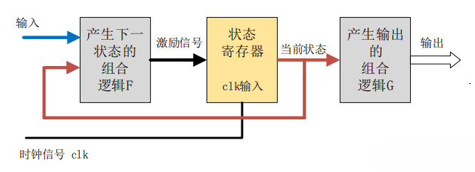
The output of a Moore state machine is only related to the current state, not to the current input.
The output remains stable for a complete clock cycle. Even if the input signal changes at this time, the output will not change. The influence of the input on the output can only be reflected in the next clock cycle. This is also an important feature of the Moore state machine: the input and output are isolated.
Mealy Type State Machine
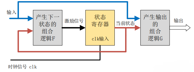
The output of a Mealy state machine depends not only on the current state, but also on the current input signal.
The output of a Mealy state machine changes immediately after the input signal changes, and the input change may occur within the clock cycle of any state. Therefore, under the same logic, the response of the Mealy state machine output to the input is one clock cycle earlier than that of the Moore state machine.
State Machine Design Flow
Draw the state transition diagram according to the design requirements, determine the type of state machine to use, and label various input and output signals, which is more helpful for programming. Generally, the most commonly used is the Mealy type 3-segment state machine. The following uses a specific example of designing an automatic vending machine to illustrate the state machine design process.
Automatic Vending Machine
The functional description of the automatic vending machine is as follows:
The drink price is 2 yuan. The vending machine can only accept 0.5 yuan and 1 yuan coins. Consider change and product dispensing. The coin insertion and product dispensing processes are carried out one at a time; there will be no situation where multiple coins are inserted at once or multiple bottles of drink are dispensed at once. Only after each round of the vending machine completes coin insertion, product dispensing, and change making can it enter a new automatic vending state.
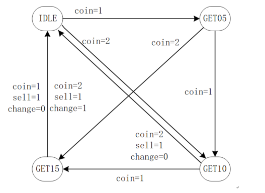
The working state transition diagram of the vending machine is shown below, including the input and output signal states.
Here, coin = 1 means a 0.5 yuan coin is inserted, and coin = 2 means a 1 yuan coin is inserted.
State Machine Design: 3-Segment Style (Recommended)
The state machine design is as follows:
- (0) First, determine the state machine encoding according to the number of states. Using encoding to assign values to state registers improves code readability.
- (1) The first segment of the state machine: sequential logic, non-blocking assignment, to transfer the state of the register.
- (2) The second segment of the state machine: combinational logic, blocking assignment, to determine the next state of the state machine based on the current state and current input.
- (3) The third segment of the state machine: sequential logic, non-blocking assignment. Because it is a Mealy state machine, determine the output signal based on the current state and current input.
Example
// 2 yuan for a bottle of drink
// only 2 coins supported: 5 jiao and 1 yuan
// finish the function of selling and changing
module vending_machine_p3 (
input clk ,
input rstn ,
input [1:0] coin , //01 for 0.5 jiao, 10 for 1 yuan
output [1:0] change ,
output sell //output the drink
);
//machine state decode
parameter IDLE = 3'd0 ;
parameter GET05 = 3'd1 ;
parameter GET10 = 3'd2 ;
parameter GET15 = 3'd3 ;
//machine variable
reg [2:0] st_next ;
reg [2:0] st_cur ;
//(1) state transfer
always @(posedge clk or negedge rstn) begin
if (!rstn) begin
st_cur <= 'b0 ;
end
else begin
st_cur <= st_next ;
end
end
//(2) state switch, using block assignment for combination-logic
//all case items need to be displayed completely
always @(*) begin
//st_next = st_cur ;//If the condition options are not fully considered, you can assign an initial value to eliminate latch
case(st_cur)
IDLE:
case (coin)
2'b01: st_next = GET05 ;
2'b10: st_next = GET10 ;
default: st_next = IDLE ;
endcase
GET05:
case (coin)
2'b01: st_next = GET10 ;
2'b10: st_next = GET15 ;
default: st_next = GET05 ;
endcase
GET10:
case (coin)
2'b01: st_next = GET15 ;
2'b10: st_next = IDLE ;
default: st_next = GET10 ;
endcase
GET15:
case (coin)
2'b01,2'b10:
st_next = IDLE ;
default: st_next = GET15 ;
endcase
default: st_next = IDLE ;
endcase
end
//(3) output logic, using non-block assignment
reg [1:0] change_r ;
reg sell_r ;
always @(posedge clk or negedge rstn) begin
if (!rstn) begin
change_r <= 2'b0 ;
sell_r <= 1'b0 ;
end
else if ((st_cur == GET15 && coin ==2'h1)
|| (st_cur == GET10 && coin ==2'd2)) begin
change_r <= 2'b0 ;
sell_r <= 1'b1 ;
end
else if (st_cur == GET15 && coin == 2'h2) begin
change_r <= 2'b1 ;
sell_r <= 1'b1 ;
end
else begin
change_r <= 2'b0 ;
sell_r <= 1'b0 ;
end
end
assign sell = sell_r ;
assign change = change_r ;
endmodule
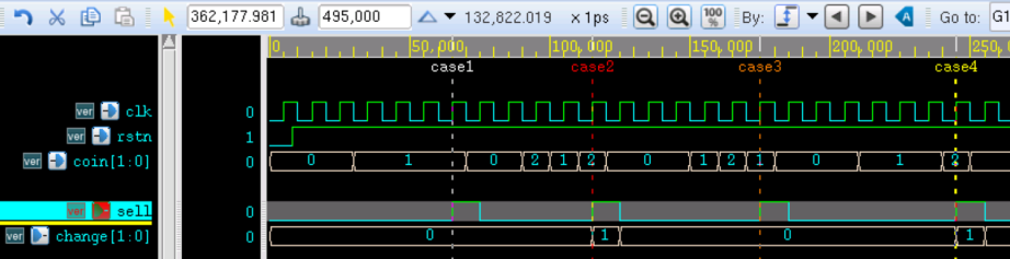
The testbench design is as follows. Four scenarios are simulated in the simulation, namely:
case1 corresponds to inserting four 0.5 yuan coins in succession; case2 corresponds to the coin insertion order of 1 yuan - 0.5 yuan - 1 yuan; case3 corresponds to the order of 0.5 yuan - 1 yuan - 0.5 yuan; case4 corresponds to the order of three consecutive 0.5 yuan coins followed by one 1 yuan coin.
Example
module test ;
reg clk;
reg rstn ;
reg [1:0] coin ;
wire [1:0] change ;
wire sell ;
//clock generating
parameter CYCLE_200MHz = 10 ; //
always begin
clk = 0 ; #(CYCLE_200MHz/2) ;
clk = 1 ; #(CYCLE_200MHz/2) ;
end
//motivation generating
reg [9:0] buy_oper ; //store state of the buy operation
initial begin
buy_oper = 'h0 ;
coin = 2'h0 ;
rstn = 1'b0 ;
#8 rstn = 1'b1 ;
@(negedge clk) ;
//case(1) 0.5 -> 0.5 -> 0.5 -> 0.5
#16 ;
buy_oper = 10'b00_0101_0101 ;
repeat(5) begin
@(negedge clk) ;
coin = buy_oper[1:0] ;
buy_oper = buy_oper >> 2 ;
end
//case(2) 1 -> 0.5 -> 1, taking change
#16 ;
buy_oper = 10'b00_0010_0110 ;
repeat(5) begin
@(negedge clk) ;
coin = buy_oper[1:0] ;
buy_oper = buy_oper >> 2 ;
end
//case(3) 0.5 -> 1 -> 0.5
#16 ;
buy_oper = 10'b00_0001_1001 ;
repeat(5) begin
@(negedge clk) ;
coin = buy_oper[1:0] ;
buy_oper = buy_oper >> 2 ;
end
//case(4) 0.5 -> 0.5 -> 0.5 -> 1, taking change
#16 ;
buy_oper = 10'b00_1001_0101 ;
repeat(5) begin
@(negedge clk) ;
coin = buy_oper[1:0] ;
buy_oper = buy_oper >> 2 ;
end
end
//(1) mealy state with 3-stage
vending_machine_p3 u_mealy_p3 (
.clk (clk),
.rstn (rstn),
.coin (coin),
.change (change),
.sell (sell)
);
//simulation finish
always begin
#100;
if ($time >= 10000) $finish ;
end
endmodule // test
The simulation results are as follows:
It can be seen from the figure that the signal sell, which represents the product dispensing action, can be normally pulled high after coin insertion is completed, and the signal change, which represents the change-making action, can also output the correct change or no-change signal according to the input coin scenario.
State Machine Modification: 2-Segment Style
Merge the descriptions of segments 2 and 3 of the 3-segment state machine, keep other parts unchanged, and the state machine becomes a 2-segment description.
The modified parts are as follows:
Example
//all using block assignment for combination-logic
reg [1:0] change_r ;
reg sell_r ;
always @(*) begin //all case items need to be displayed completely
case(st_cur)
IDLE: begin
change_r = 2'b0 ;
sell_r = 1'b0 ;
case (coin)
2'b01: st_next = GET05 ;
2'b10: st_next = GET10 ;
default: st_next = IDLE ;
endcase // case (coin)
end
GET05: begin
change_r = 2'b0 ;
sell_r = 1'b0 ;
case (coin)
2'b01: st_next = GET10 ;
2'b10: st_next = GET15 ;
default: st_next = GET05 ;
endcase // case (coin)
end
GET10:
case (coin)
2'b01: begin
st_next = GET15 ;
change_r = 2'b0 ;
sell_r = 1'b0 ;
end
2'b10: begin
st_next = IDLE ;
change_r = 2'b0 ;
sell_r = 1'b1 ;
end
default: begin
st_next = GET10 ;
change_r = 2'b0 ;
sell_r = 1'b0 ;
end
endcase // case (coin)
GET15:
case (coin)
2'b01: begin
st_next = IDLE ;
change_r = 2'b0 ;
sell_r = 1'b1 ;
end
2'b10: begin
st_next = IDLE ;
change_r = 2'b1 ;
sell_r = 1'b1 ;
end
default: begin
st_next = GET15 ;
change_r = 2'b0 ;
sell_r = 1'b0 ;
end
endcase
default: begin
st_next = IDLE ;
change_r = 2'b0 ;
sell_r = 1'b0 ;
end
endcase
end
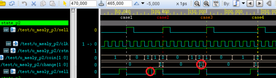
Instantiate the newly modified module above into the 3-segment testbench to perform simulation. The results are as follows:
It can be seen from the figure that the product dispensing signal sell and the change signal change are one clock cycle earlier than the output of the 3-segment state machine. This is because the output signals are all blocking assignments.
As shown in the red circle parts in the figure, glitch pulses appear on the output signals. This is because the input signals are asynchronous, and the output signals are combinational logic outputs without clock drive.
In practice, if the input signals are synchronized with the clock, such glitch pulses will not appear. If the input signals are asynchronous, the signals should be synchronized first.
State Machine Modification: 1-Segment Style (Use with Caution)
Merge the descriptions of segments 1, 2, and 3 of the 3-segment state machine, and the state machine becomes a 1-segment description.
The modified parts are as follows:
Example
//(1) using one state-variable do describe
reg [1:0] change_r ;
reg sell_r ;
always @(posedge clk or negedge rstn) begin
if (!rstn) begin
st_cur <= 'b0 ;
change_r <= 2'b0 ;
sell_r <= 1'b0 ;
end
else begin
case(st_cur)
IDLE: begin
change_r <= 2'b0 ;
sell_r <= 1'b0 ;
case (coin)
2'b01: st_cur <= GET05 ;
2'b10: st_cur <= GET10 ;
endcase
end
GET05: begin
case (coin)
2'b01: st_cur <= GET10 ;
2'b10: st_cur <= GET15 ;
endcase
end
GET10:
case (coin)
2'b01: st_cur <= GET15 ;
2'b10: begin
st_cur <= IDLE ;
sell_r <= 1'b1 ;
end
endcase
GET15:
case (coin)
2'b01: begin
st_cur <= IDLE ;
sell_r <= 1'b1 ;
end
2'b10: begin
st_cur <= IDLE ;
change_r <= 2'b1 ;
sell_r <= 1'b1 ;
end
endcase
default: begin
st_cur <= IDLE ;
end
endcase // case (st_cur)
end // else: !if(!rstn)
end
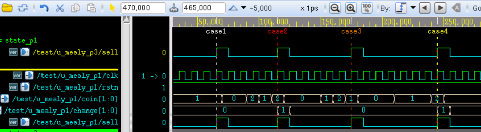
Instantiate the newly modified module above into the 3-segment testbench to perform simulation. The results are as follows:
It can be seen from the figure that the output signals are exactly the same as those of the 3-segment state machine.
The disadvantage of the 1-segment state machine is that many kinds of logic are mixed together, making later maintenance difficult. When the state machine and output signals are few, this description style can be tried.
State Machine Modification: Moore Type
If a Moore state machine is used to describe the working flow of the vending machine, then 2 more state encodings need to be added to describe the input signal and state machine state when the Mealy state machine outputs.
The Verilog code of the automatic vending machine described by the 3-segment Moore state machine is as follows:
Example
input clk ,
input rstn ,
input [1:0] coin , //01 for 0.5 jiao, 10 for 1 yuan
output [1:0] change ,
output sell //output the drink
);
//machine state decode
parameter IDLE = 3'd0 ;
parameter GET05 = 3'd1 ;
parameter GET10 = 3'd2 ;
parameter GET15 = 3'd3 ;
// new state for moore state-machine
parameter GET20 = 3'd4 ;
parameter GET25 = 3'd5 ;
//machine variable
reg [2:0] st_next ;
reg [2:0] st_cur ;
//(1) state transfer
always @(posedge clk or negedge rstn) begin
if (!rstn) begin
st_cur <= 'b0 ;
end
else begin
st_cur <= st_next ;
end
end
//(2) state switch, using block assignment for combination-logic
always @(*) begin //all case items need to be displayed completely
case(st_cur)
IDLE:
case (coin)
2'b01: st_next = GET05 ;
2'b10: st_next = GET10 ;
default: st_next = IDLE ;
endcase
GET05:
case (coin)
2'b01: st_next = GET10 ;
2'b10: st_next = GET15 ;
default: st_next = GET05 ;
endcase
GET10:
case (coin)
2'b01: st_next = GET15 ;
2'b10: st_next = GET20 ;
default: st_next = GET10 ;
endcase
GET15:
case (coin)
2'b01: st_next = GET20 ;
2'b10: st_next = GET25 ;
default: st_next = GET15 ;
endcase
GET20: st_next = IDLE ;
GET25: st_next = IDLE ;
default: st_next = IDLE ;
endcase // case (st_cur)
end // always @ (*)
// (3) output logic,
// one cycle delayed when using non-block assignment
reg [1:0] change_r ;
reg sell_r ;
always @(posedge clk or negedge rstn) begin
if (!rstn) begin
change_r <= 2'b0 ;
sell_r <= 1'b0 ;
end
else if (st_cur == GET20 ) begin
sell_r <= 1'b1 ;
end
else if (st_cur == GET25) begin
change_r <= 2'b1 ;
sell_r <= 1'b1 ;
end
else begin
change_r <= 2'b0 ;
sell_r <= 1'b0 ;
end
end
assign sell = sell_r ;
assign change = change_r ;
endmodule
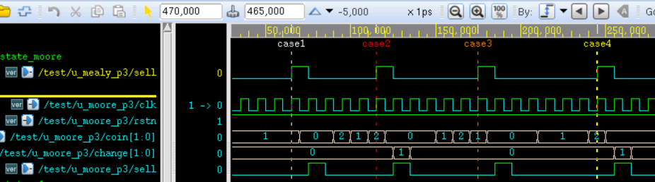
Instantiate the modified Moore state machine above into the 3-segment testbench to perform simulation. The results are as follows:
It can be seen from the figure that the output signal is delayed by one clock cycle compared with the Mealy type 3-segment state machine. This is because entering the newly added encoding state machine requires a delay of one clock cycle. At this time, using non-blocking assignment for the output will cause the final output signal to be delayed by one clock cycle. This is also a characteristic of the Moore state machine.
When assigning the output signal, using blocking assignment can advance it by one clock cycle.
The output logic is modified as follows.
Example
// (3.2) output logic, using block assignment
reg [1:0] change_r ;
reg sell_r ;
always @(*) begin
change_r = 'b0 ;
sell_r = 'b0 ; //not list all condition, initializing them
if (st_cur == GET20 ) begin
sell_r = 1'b1 ;
end
else if (st_cur == GET25) begin
change_r = 2'b1 ;
sell_r = 1'b1 ;
end
end
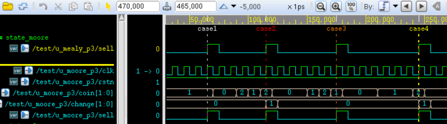
The simulation results of blocking assignment for the output signal are as follows:
It can be seen from the figure that the output signal is now consistent with the 3-segment Mealy state machine.
Source Code Download
Download