Keywords: testbench, simulation, file read/write
After the Verilog code design is completed, an important step still needs to be carried out, namely logic functional simulation. The simulation stimulus file is called a testbench and is placed at the top level of the design modules so that the modules can be systematically instantiated and invoked for simulation.
It is no exaggeration to say that for slightly complex Verilog designs, if simulation is not performed, more than 99.9999% of designs will not work correctly, even for experienced veterans. It cannot be said that simulation is more important than design, but generally speaking, simulation takes more time than design. Sometimes, considering various application scenarios, writing a testbench can be more complex than Verilog design. Therefore, the digital circuit industry specifically distinguishes design engineers and verification engineers.
Below, we will have a brief study of the testbench.
Testbench structure breakdown
The general structure of a testbench is as follows: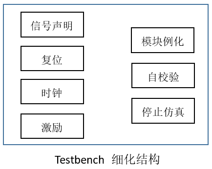
In fact, the most basic structure of a testbench includes signal declaration, stimulus, and module instantiation.
Depending on the complexity of the design, clock and reset parts need to be introduced. Of course, for more complex designs, the stimulus part will also be more complex. According to your verification needs, choose whether self-checking and simulation termination parts are needed.
Of course, the reset and clock generation parts can also be regarded as stimulus, so they can all be implemented in a single statement block. The self-check result can also be used as a condition for ending the simulation.
In actual simulation, you can write the testbench according to your own personal habits; this is just a personal summary.
Testbench simulation example
Many testbenches have already been written in the previous chapters. In fact, their structures are roughly the same.
Below, we give a simple example of data concatenation and conduct a specific analysis of the testbench.
A functional module that concatenates 2-bit data into 8-bit data is described as follows:
Example
(
input clk ,
input rstn ,
input [1:0] din , //data in
input din_en ,
output [7:0] dout ,
output dout_en //data out
);
// data shift and counter
reg [7:0] data_r ;
reg [1:0] state_cnt ;
always @(posedge clk or negedge rstn) begin
if (!rstn) begin
state_cnt <= 'b0 ;
data_r <= 'b0 ;
end
else if (din_en) begin
state_cnt <= state_cnt + 1'b1 ; //Data counting
data_r <= {data_r[5:0], din} ; //Data concatenation
end
else begin
state_cnt <= 'b0 ;
end
end
assign dout = data_r ;
// data output en
reg dout_en_r ;
always @(posedge clk or negedge rstn) begin
if (!rstn) begin
dout_en_r <= 'b0 ;
end
//When the count is 3 and the 4th data is input, synchronously output the data output enable signal
else if (state_cnt == 2'd3 & din_en) begin
dout_en_r <= 1'b1 ;
end
else begin
dout_en_r <= 1'b0 ;
end
end
//Here, dout_en is not directly declared as a reg variable; instead, it is assigned via assign using related registers
assign dout_en = dout_en_r;
endmodule
The corresponding testbench description is as follows, with file read/write statements added:
Example
//============== (1) ==================
//signals declaration
module test ;
reg clk;
reg rstn ;
reg [1:0] din ;
reg din_en ;
wire [7:0] dout ;
wire dout_en ;
//============== (2) ==================
//clock generating
real CYCLE_200MHz = 5 ; //
always begin
clk = 0 ; #(CYCLE_200MHz/2) ;
clk = 1 ; #(CYCLE_200MHz/2) ;
end
//============== (3) ==================
//reset generating
initial begin
rstn = 1'b0 ;
#8 rstn = 1'b1 ;
end
//============== (4) ==================
//motivation
int fd_rd ;
reg [7:0] data_in_temp ; //for self check
reg [15:0] read_temp ; //8bit ascii data, 8bit \n
initial begin
din_en = 1'b0 ; //(4.1)
din = 'b0 ;
open_file("../tb/data_in.dat", "r", fd_rd); //(4.2)
wait (rstn) ; //(4.3)
# CYCLE_200MHz ;
//read data from file
while (! $feof(fd_rd) ) begin //(4.4)
@(negedge clk) ;
$fread(read_temp, fd_rd);
din = read_temp[9:8] ;
data_in_temp = {data_in_temp[5:0], din} ;
din_en = 1'b1 ;
end
//stop data
@(posedge clk) ; //(4.5)
#2 din_en = 1'b0 ;
end
//open task
task open_file;
input string file_dir_name ;
input string rw ;
output int fd ;
fd = $fopen(file_dir_name, rw);
if (! fd) begin
$display("--- iii --- Failed to open file: %s", file_dir_name);
end
else begin
$display("--- iii --- %s has been opened successfully.", file_dir_name);
end
endtask
//============== (5) ==================
//module instantiation
data_consolidation u_data_process
(
.clk (clk),
.rstn (rstn),
.din (din),
.din_en (din_en),
.dout (dout),
.dout_en (dout_en)
);
//============== (6) ==================
//auto check
reg [7:0] err_cnt ;
int fd_wr ;
initial begin
err_cnt = 'b0 ;
open_file("../tb/data_out.dat", "w", fd_wr);
forever begin
@(negedge clk) ;
if (dout_en) begin
$fdisplay(fd_wr, "%h", dout);
end
end
end
always @(posedge clk) begin
#1 ;
if (dout_en) begin
if (data_in_temp != dout) begin
err_cnt = err_cnt + 1'b1 ;
end
end
end
//============== (7) ==================
//simulation finish
always begin
#100;
if ($time >= 10000) begin
if (!err_cnt) begin
$display("-------------------------------------");
$display("Data process is OK!!!");
$display("-------------------------------------");
end
else begin
$display("-------------------------------------");
$display("Error occurs in data process!!!");
$display("-------------------------------------");
end
#1 ;
$finish ;
end
end
endmodule // test
The simulation results are as follows. As can be seen from the figure, the data integration function design meets the requirements:
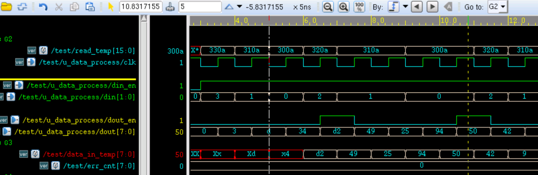
Detailed testbench analysis
1) Signal declaration
When declaring a testbench module, it is generally not necessary to declare ports, because stimulus signals are generally inside the testbench module and there are no external signals.
The declared variables should all correspond to the ports of the module under test. Of course, the variables do not have to have the same names as the ports of the module under test. However, variables corresponding to the input ports of the module under test should be declared as reg type, such as clk, rstn, etc., and variables corresponding to the output ports should be declared as wire type, such as dout, dout_en.
2) Clock generation
There are many ways to generate a clock; for example, the following two generation methods can also be used for reference.
Example
always #(CYCLE_200MHz/2) clk = ~clk;
initial begin
clk = 0 ;
forever begin
#(CYCLE_200MHz/2) clk = ~clk;
end
end
It should be noted that when using the inversion method to generate a clock, the clk register must be assigned an initial value.
When using the parameter method to specify time delays, if the delay parameter is a floating-point number, this parameter should not be declared as a parameter type. For example, in the sample, the variable CYCLE_200MHz has a value of 2.5. If its variable type is parameter, the final generated clock period is likely to be 4ns. Of course, the precision of timescale also needs to be increased; the unit and precision cannot be the same, otherwise the fractional part of the time delay assignment will not take effect.
3) Reset generation
The reset logic is relatively simple. Generally, the initial value is assigned 0, and then after a small delay, reset is set to 1.
Most simulations here use active-low reset.
4) Stimulus part
What kind of input signals the stimulus part should generate is designed according to the needs of the module under test.
In this example:
- (4.1) Initialize the input signals of the module under test to prevent the appearance of unknown value X. For generating the stimulus data, we need to read from a data file.
- At (4.2), a task is used to open a file. As long as the specified file exists, a non-zero handle signal fp_rd can be obtained. fp_rd specifies the starting address of the file data.
- The operation at (4.3) is to wait until after reset, so that the system has a safe and stable testable state.
- At (4.4), it begins to read data and apply stimulus in a loop. Sending data on the falling edge of the clock is so that the module under test can better sample the data on the rising edge.
Using the system task $fread, the read 16-bit data variable is fed into the read_temp buffer through the handle signal fd_rd.
The screenshot of the first few data items in the input data file is as follows. Because $fread can only read binary files, the first line of the input file corresponds to the ASCII code 330a. Therefore, to get the data 3 in the file, we should take the data from bit 9 to bit 8 of the variable read_temp.
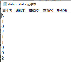
The signal data_in_temp is a subsequent integration of the input data signal. Later, the verification module will use it as a reference to determine whether the simulation is normal and whether the module design is correct.
- At (4.5), choosing to stop input data after delaying 2 cycles on the rising edge of the clock is so that the module under test can normally sample the last data enable signal and integrate the data correctly.
When the amount of data is relatively small, you can use the system task $readmemh in Verilog to directly read hexadecimal data line by line. Keeping the data and format in the file data_in.dat unchanged, this stimulus part can be described as:
Example
reg [7:0] data_in_temp ; //for self check
integer k1 ;
initial begin
din_en = 1'b0 ;
din = 'b0 ;
$readmemh("../tb/data_in.dat", data_mem);
wait (rstn) ;
# CYCLE_200MHz ;
//read data from file
for(k1=0; k1<40; k1=k1+1) begin
@(negedge clk) ;
din = data_mem[k1] ;
data_in_temp = {data_in_temp[5:0], din} ;
din_en = 1'b1 ;
end
//stop data
@(posedge clk) ;
#2 din_en = 1'b0 ;
end
5) Module instantiation
Here, the signal variables declared at the beginning of the testbench are used to instantiate and connect the module under test.
6) Self-checking
If the design is relatively simple, it is entirely possible to determine whether the design is correct through the waveforms of the input and output signals, and this part can be completely removed. If there is a lot of data, sometimes observing with the naked eye cannot effectively judge the correctness of the design. At this time, adding a self-checking module will greatly increase the simulation efficiency.
In the example, when the data output enable dout_en is active, we compare the output data dout with the reference data read_temp (generated by the stimulus part) and put the comparison result into the signal err_cnt. Finally, we can intuitively judge the correctness of the design by observing whether the err_cnt signal is 0.
Of course, as shown in the example, we can also write the data to a corresponding file and use other methods for comparison.
7) Ending the simulation
If we do not add the simulation termination part, the simulation will run indefinitely, and waveforms that are too long are sometimes inconvenient to analyze. Verilog provides the system task $finish to stop the simulation.
Before stopping the simulation, the self-check results can be displayed in the terminal using the system task $display.
File read/write options
The format of the system task $fopen used to open a file is as follows:
fd = $fopen("<name_of_file>", "mode")
Similar to the C language, the meaning of the opening mode option "mode" is as follows:
| r | Open a text file read-only, only allowing data reads. |
|---|---|
| w | Open a text file write-only, only allowing data writes. If the file exists, the original file contents will be deleted. If the file does not exist, a new file will be created. |
| a | Open a text file for appending and write data at the end of the file. If the file does not exist, a new file will be created. |
| rb | Open a binary file read-only, only allowing data reads. |
| wb | Open or create a binary file write-only, only allowing data writes. |
| ab | Open a binary file for appending and write data at the end of the file. |
| r+ | Open a text file for reading and writing, allowing both read and write. |
| w+ | Open or create a text file for reading and writing, allowing read and write. If the file exists, the original file contents will be deleted. If the file does not exist, a new file will be created. |
| a+ | Open a text file for reading and writing, allowing read and write. If the file does not exist, a new file will be created. Reading the file starts from the beginning of the file, and writing can only be in append mode. |
| rb+ | Open a binary text file for reading and writing, with functionality similar to "r+". |
| wb+ | Open or create a binary text file for reading and writing, with functionality similar to "w+". |
| ab+ | Open a binary text file for reading and writing, with functionality similar to "a+". |
Source code download
Download