Keywords: synchronous reset, asynchronous reset
To ensure that the system has a clear and stable initial state after power-on, or that it can recover to a normal initial state when the system operation state is disturbed, a reset circuit module is necessary in digital system design. Abnormal reset circuits may cause functional abnormalities of the entire system, so to a certain extent, the importance of the reset circuit is no less than that of the clock circuit.
Reset circuits can be classified into synchronous reset and asynchronous reset.
Synchronous Reset
Synchronous reset means that the reset signal is effective when the active edge of the clock arrives. Without a clock, no matter how the reset signal changes, the circuit will not perform a reset operation.
A typical code description of synchronous reset is as follows:
Example
input rstn, // synchronous reset signal
input clk, // clock
input din, // input data
output reg dout // output data
);
always @(posedge clk) begin // reset signal should not be added to the sensitivity list
if(!rstn) dout <= 1'b0 ; // rstn signal is synchronous with clock clk
else dout <= din ;
end
endmodule
This descriptive code is often synthesized into the following circuit:
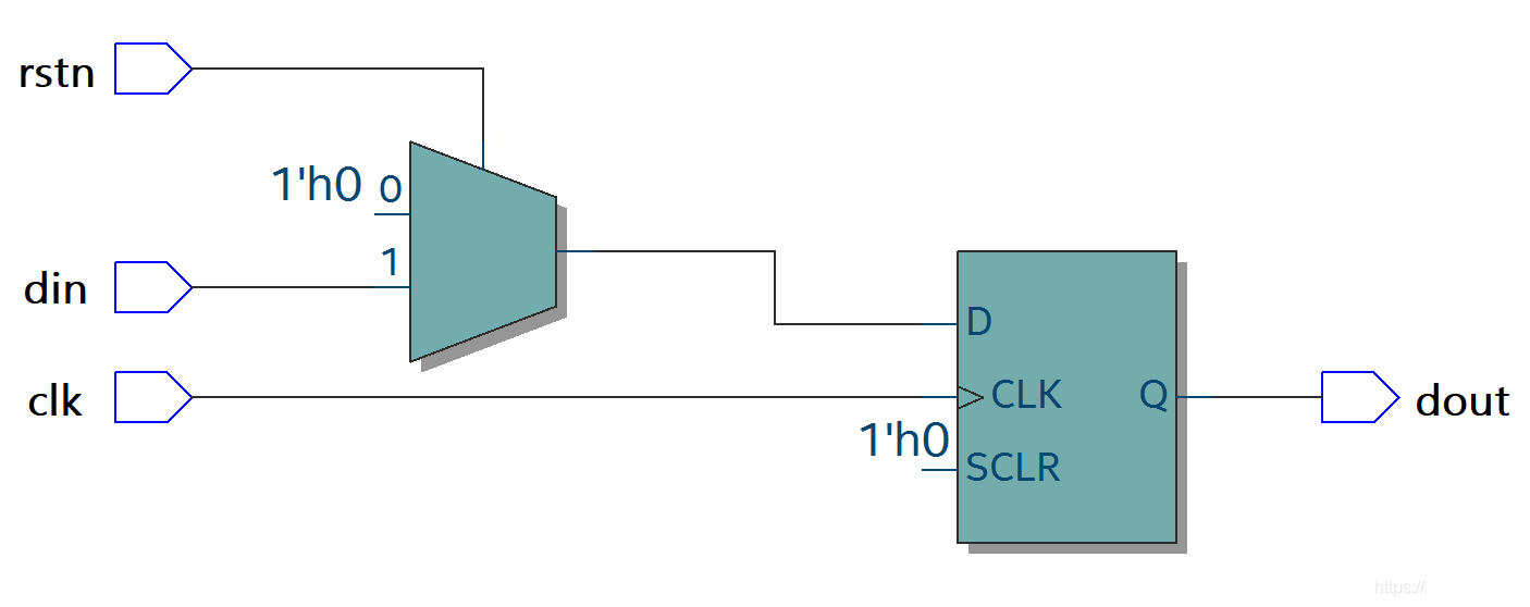
Advantages of synchronous reset: signals are synchronous, can filter glitches in the reset signal, and facilitate timing analysis.
Disadvantages of synchronous reset: most flip-flop cells do not have a synchronous reset terminal, so using synchronous reset consumes additional logic resources. Also, the width of the reset signal must be greater than one clock cycle, otherwise the reset signal may be missed.
Asynchronous Reset
Asynchronous reset means that regardless of whether the clock arrives, as long as the reset signal is valid, the circuit will perform a reset operation.
A typical code description of asynchronous reset is as follows:
Example
input rstn, // asynchronous reset signal
input clk, // clock
input din, // input data
output reg dout // output data
);
// reset signal should be added to the sensitivity list
always @(posedge clk or negedge rstn) begin
if(!rstn) dout <= 1'b0 ; // rstn signal is asynchronous with clock clk
else dout <= din ;
end
endmodule
This code is often synthesized into the following circuit:
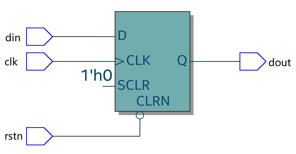
Advantages of asynchronous reset: most flip-flop cells have an asynchronous reset terminal, which does not occupy extra logic resources. Moreover, the asynchronous reset signal is directly referenced without processing, making the design relatively simple and signal recognition fast and convenient.
Disadvantages of asynchronous reset: there is no definite timing relationship between the reset signal and the clock signal, so asynchronous reset can easily cause timing violations of removal and recovery. Also, asynchronous reset is easily disturbed by glitches, causing unexpected reset operations.
Asynchronous Reset Synchronous Release
Considering factors such as design and resources, asynchronous reset is generally used in digital system design.
To eliminate the defects of asynchronous reset, reset circuits often adopt the design method of "asynchronous reset, synchronous release". That is, when the reset signal arrives, it is not synchronized by the clock signal; when the reset signal is released, it needs to be synchronized with the clock signal.
A typical code description of asynchronous reset, synchronous release is as follows:
Example
input rstn, // asynchronous reset signal
input clk, // clock
input din, // input data
output reg dout // output data
);
reg rstn_r1, rstn_r2;
always @ (posedge clk or negedge rstn) begin
if (!rstn) begin
rstn_r1 <= 1'b0; // asynchronous reset
rstn_r2 <= 1'b0;
end
else begin
rstn_r1 <= 1'b1; // synchronous release
rstn_r2 <= rstn_r1; // synchronize by delaying (beating); the timing difference can be delayed by a few more beats
end
end
// Use rstn_r2 as synchronous reset; the reset signal can be added to the sensitivity list
always @ (posedge clk or negedge rstn_r2) begin
if (!rstn_r2) dout <= 1'b0; // synchronous reset
else dout <= din;
end
endmodule
This code description is often synthesized into the following circuit:
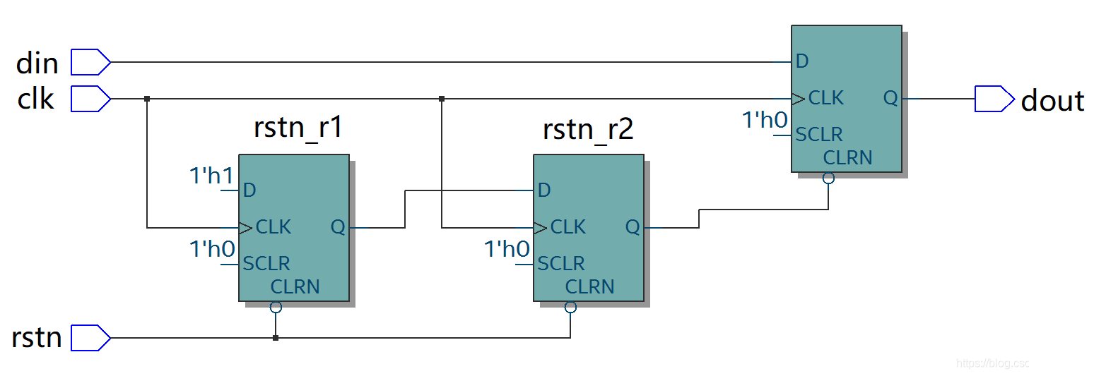
It should be noted that reset circuits consume more hardware logic and area resources, increasing the complexity of system design. Flip-flops without a reset terminal also have relatively higher performance. Therefore, in some digital designs where initial values do not affect logical correctness—such as some data processing parts in data paths, or some registers in high-speed pipelines—considering removing the reset can achieve optimal performance.
For convenient and fast simulation of other functions of non-reset logic, the resets in all digital designs in this tutorial are introduced as asynchronous resets from the testbench, without considering the timing issues of the reset circuit. When actually designing digital systems, the reset circuit must be designed separately, carefully, and prudently.