Keywords: even division, odd division, half-integer division, fractional division
When first learning Verilog, many modules are composed of counters and dividers, such as PWM pulse width modulation, frequency counters, etc. Division logic is often implemented through counting logic. This section mainly provides a brief summary of even division, odd division, half-integer division, and fractional division.
Even division
By connecting the inverting output of a flip-flop back to its input, a simple divide-by-2 circuit can be constructed.
Cascading based on this can form divide-by-4 and divide-by-8 circuits.
The circuit implementation is shown in the figure below. When describing it in Verilog, simple inversion logic is sufficient.
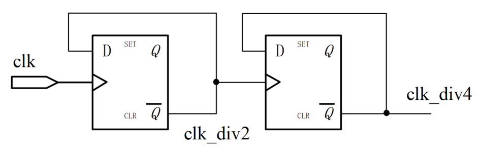
If the even division factor is too large, it is necessary to cyclically count the division factor N. When the count period reaches the middle value N/2 of the division factor, the clock is toggled, which ensures a 50% duty cycle for the divided clock. Because it is even division, counting can also be performed cyclically up to the middle value N/2.
An example of Verilog description for even division is as follows.
Example
# (parameter DIV_CLK = 10 )
(
input rstn ,
input clk,
output clk_div2,
output clk_div4,
output clk_div10
);
//divide by 2
reg clk_div2_r ;
always @(posedge clk or negedge rstn) begin
if (!rstn) begin
clk_div2_r <= 'b0 ;
end
else begin
clk_div2_r <= ~clk_div2_r ;
end
end
assign clk_div2 = clk_div2_r ;
//divide by 4
reg clk_div4_r ;
always @(posedge clk_div2 or negedge rstn) begin
if (!rstn) begin
clk_div4_r <= 'b0 ;
end
else begin
clk_div4_r <= ~clk_div4_r ;
end
end
assign clk_div4 = clk_div4_r ;
//N/2 count
reg [3:0] cnt ;
always @(posedge clk or negedge rstn) begin
if (!rstn) begin
cnt <= 'b0 ;
end
else if (cnt == (DIV_CLK/2)-1) begin
cnt <= 'b0 ;
end
else begin
cnt <= cnt + 1'b1 ;
end
end
//output clock
reg clk_div10_r ;
always @(posedge clk or negedge rstn) begin
if (!rstn) begin
clk_div10_r <= 1'b0 ;
end
else if (cnt == (DIV_CLK/2)-1 ) begin
clk_div10_r <= ~clk_div10_r ;
end
end
assign clk_div10 = clk_div10_r ;
endmodule
In the testbench, it is only necessary to provide the stimulus clock and other signals, so it will not be listed here.
The simulation results are as follows.

Odd division
If odd division does not require a 50% duty cycle, it can be performed in the same way as even division. That is, the counter cyclically counts the division factor N, and then a certain duty cycle is selected based on the count value to output the divided clock.
If the high and low levels of the odd-division output clock differ by only one cycle, the source clock's double-edge characteristic can be used, combined with an "AND operation" or "OR operation", to adjust the duty cycle of the divided clock to 50%.
OR operation to adjust duty cycle
The timing diagram for generating a divide-by-3 clock with a 50% duty cycle using the "OR operation" is shown below.
Use the rising edge of the source clock to generate a divide-by-3 clock with a high level of 1 cycle and a low level of 2 cycles.
Use the falling edge of the source clock to generate a divide-by-3 clock with a high level of 1 cycle and a low level of 2 cycles.
The two divide-by-3 clocks should be generated under the same counter value but at different edges, with a phase difference of half a clock cycle. Then, by performing an "OR operation" on the two clocks, a divide-by-3 clock with a 50% duty cycle can be obtained.
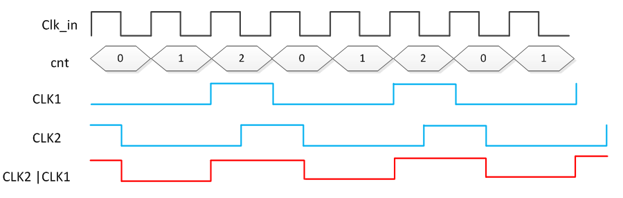
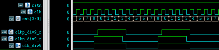
Similarly, for divide-by-9, it is necessary to generate divide-by-9 clocks with 4 high-level cycles and 5 low-level cycles on both the rising and falling edges, and then perform an "OR operation" on the two clocks. The Verilog description is as follows.
Example
#(parameter DIV_CLK = 9)
(
input rstn ,
input clk,
output clk_div9
);
//counter
reg [3:0] cnt ;
always @(posedge clk or negedge rstn) begin
if (!rstn) begin
cnt <= 'b0 ;
end
else if (cnt == DIV_CLK-1) begin
cnt <= 'b0 ;
end
else begin
cnt <= cnt + 1'b1 ;
end
end
//generate divide-by-9 on rising edge
reg clkp_div9_r ;
always @(posedge clk or negedge rstn) begin
if (!rstn) begin
clkp_div9_r <= 1'b0 ;
end
else if (cnt == (DIV_CLK>>1)-1 ) begin //count 4-8 as low level
clkp_div9_r <= 0 ;
end
else if (cnt == DIV_CLK-1) begin //count 0-3 as high level
clkp_div9_r <= 1 ;
end
end
//generate divide-by-9 on falling edge
reg clkn_div9_r ;
always @(negedge clk or negedge rstn) begin
if (!rstn) begin
clkn_div9_r <= 1'b0 ;
end
else if (cnt == (DIV_CLK>>1)-1 ) begin
clkn_div9_r <= 0 ;
end
else if (cnt == DIV_CLK-1) begin
clkn_div9_r <= 1 ;
end
end
//OR operation, usually using basic logic cell library
// or (clk_div9, clkp_div9_r, clkn_div9_r) ;
assign clk_div9 = clkp_div9_r | clkn_div9_r ;
endmodule
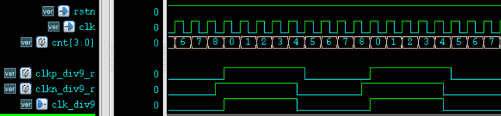
The simulation results are as follows.
AND operation to adjust duty cycle
The timing diagram for generating a divide-by-3 clock with a 50% duty cycle using the "AND operation" is shown below.
Use the rising edge of the source clock to generate a divide-by-3 clock with a high level of 2 cycles and a low level of 1 cycle.
Use the falling edge of the source clock to generate a divide-by-3 clock with a high level of 2 cycles and a low level of 1 cycle.
The two divide-by-3 clocks should be generated under the same counter value but at different edges, with a phase difference of half a clock cycle. Then, by performing an "AND operation" on the two clocks, a divide-by-3 clock with a 50% duty cycle can be obtained.
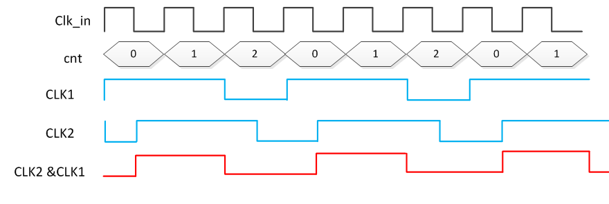
Similarly, for divide-by-9, it is necessary to generate divide-by-9 clocks with 5 high-level cycles and 4 low-level cycles on both the rising and falling edges, and then perform an "AND operation" on the two clocks. The Verilog description is as follows.
Example
#( parameter DIV_CLK = 9 )
(
input rstn ,
input clk,
output clk_div9
);
//counter
reg [3:0] cnt ;
always @(posedge clk or negedge rstn) begin
if (!rstn) begin
cnt <= 'b0 ;
end
else if (cnt == DIV_CLK-1) begin
cnt <= 'b0 ;
end
else begin
cnt <= cnt + 1'b1 ;
end
end
//generate divide-by-9 on rising edge
reg clkp_div9_r ;
always @(posedge clk or negedge rstn) begin
if (!rstn) begin
clkp_div9_r <= 1'b0 ;
end
else if (cnt == (DIV_CLK>>1) ) begin //count 5-8 as low level
clkp_div9_r <= 0 ;
end
else if (cnt == DIV_CLK-1) begin //count 0-4 as high level
clkp_div9_r <= 1 ;
end
end
//generate divide-by-9 on falling edge
reg clkn_div9_r ;
always @(negedge clk or negedge rstn) begin
if (!rstn) begin
clkn_div9_r <= 1'b0 ;
end
else if (cnt == (DIV_CLK>>1) ) begin
clkn_div9_r <= 0 ;
end
else if (cnt == DIV_CLK-1) begin
clkn_div9_r <= 1 ;
end
end
//AND operation, usually using basic logic cell library
//and (clk_div9, clkp_div9_r, clkn_div9_r) ;
assign clk_div9 = clkp_div9_r & clkn_div9_r ;
endmodule
The simulation results are as follows.
Half-integer division
By using the double-edge logic of the clock, half-integer division can be performed. However, no matter how it is adjusted, the duty cycle of half-integer division cannot be 50%. There are many methods for half-integer division; here only one method similar to the duty-cycle adjustment for odd division is introduced.
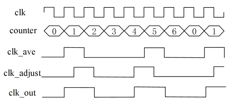
- (1) For example, when performing divide-by-3.5, the counter cyclically counts to 7, generating two divided clocks composed of 4 and 3 source clock cycles respectively. From the perspective that 2 divided clocks are generated from 7 source clocks, the process completes a divide-by-3.5 operation, but each divided clock is not strictly a divide-by-3.5 result.
- (2) Next, adjust the divided clocks with uneven periods. In one counting cycle, generate two divided clocks composed of 4 and 3 source clock cycles respectively on the falling edge of the source clock. Compared with the two uneven-period clocks generated the first time, the phase of the two clocks generated this time is delayed by half a source clock period and advanced by half a source clock period, respectively.
- (3) By performing an "OR operation" on the two generated clocks, a divide-by-3.5 clock with uniform period can be obtained. The waveform diagram of the divided clock is shown below.
The Verilog description of divide-by-3.5 clock is as follows.
Example
input rstn ,
input clk,
output clk_div3p5
);
//counter
parameter MUL2_DIV_CLK = 7 ;
reg [3:0] cnt ;
always @(posedge clk or negedge rstn) begin
if (!rstn) begin
cnt <= 'b0 ;
end
else if (cnt == MUL2_DIV_CLK-1) begin //count up to 2 times the division ratio
cnt <= 'b0 ;
end
else begin
cnt <= cnt + 1'b1 ;
end
end
reg clk_ave_r ;
always @(posedge clk or negedge rstn) begin
if (!rstn) begin
clk_ave_r <= 1'b0 ;
end
//first cycle: 4 source clk cycle
else if (cnt == 0) begin
clk_ave_r <= 1 ;
end
//2nd cycle: 3 source clk cycle
else if (cnt == (MUL2_DIV_CLK/2)+1) begin
clk_ave_r <= 1 ;
end
else begin
clk_ave_r <= 0 ;
end
end
//adjust
reg clk_adjust_r ;
always @(negedge clk or negedge rstn) begin
if (!rstn) begin
clk_adjust_r <= 1'b0 ;
end
//this clock is only for adjusting consistent duty cycle
else if (cnt == 1) begin
clk_adjust_r <= 1 ;
end
//this clock is only for adjusting consistent precise division ratio
else if (cnt == (MUL2_DIV_CLK/2)+1 ) begin
clk_adjust_r <= 1 ;
end
else begin
clk_adjust_r <= 0 ;
end
end
assign clk_div3p5 = clk_adjust_r | clk_ave_r ;
endmodule
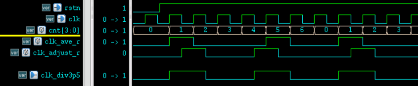
The simulation results are as follows.
Fractional division
Basic principle
Irregular fractional division cannot make every divided clock cycle an exact fractional multiple of the source clock cycle, nor can it make the duty cycle of the divided clock 50%, because Verilog cannot perform fractional counting on the clock. Similar to the "average frequency" concept introduced in the first division step of half-integer division, fractional division is also implemented based on variable division and multiple averaging methods.
For example, for divide-by-7.6, it is sufficient to ensure that the time of 76 source clock cycles equals the time of 10 divided clock cycles. In this case, it is necessary to perform 6 divide-by-8 operations and 4 divide-by-7 operations within 76 source clock cycles. For another example, for divide-by-5.76, it is necessary to perform 76 divide-by-6 operations and 24 divide-by-5 operations within 576 source clock cycles.
The calculation process of these division parameters is explained below.
When performing divide-by-7, it can be understood as performing 10 divide-by-7 operations within 70 source clock cycles. If 10 divisions are still performed within 76 source clock cycles, it is equivalent to distributing the extra 6 source clock cycles into the 70 source clock cycles, thereby completing the divide-by-7.6 operation. In the division process, 6 divided clocks must be obtained by divide-by-8, while the remaining 4 divided clocks will maintain the original divide-by-7 state.
Many places give a system of two linear equations for calculating these division parameters, as shown below. The principle is the same as the analysis above, and it is recommended to master the calculation process described above.
7N + 8M = 76
N  + M   = 10
Here, 7 is the integer division factor, N is the number of times the integer division is performed; 8 is the division factor obtained by adding one to the integer division factor, and M is the number of times this division is performed.
Averaging principle
Taking divide-by-7.6 as an example, the implementation order of divide-by-7 and divide-by-8 generally has the following 4 cases:
- (1) First perform divide-by-7 4 times, then perform divide-by-8 6 times;
- (2) First perform divide-by-8 6 times, then perform divide-by-7 4 times;
- (3) Evenly insert the 4 divide-by-7 operations into the 6 divide-by-8 operations;
- (4) Evenly insert the 6 divide-by-8 operations into the 4 divide-by-7 operations.
The first two methods result in uneven clock frequencies and large phase jitter, so the latter two average-insertion methods are generally used for fractional division.
Average insertion can be implemented by accumulating the difference in division counts. The implementation process of divide-by-7.6 is as follows:
- (1) The first division count difference is 76-10*7 = 6 < 10, so the first division is divide-by-7.
- (2) The second accumulated difference result is 6+6=12 > 10, so the second division uses divide-by-8, and the difference is modified to 12-10=2.
- (3) The third accumulated difference result is 2+6=8 < 10, so the third division uses divide-by-7.
- (4) The fourth accumulated difference result is 8+6=14 > 10, so the fourth division uses divide-by-8, and the difference is modified to 14-10=4.
By analogy, complete the process of evenly inserting six divide-by-8 operations into four divide-by-7 operations.
The following table shows the frequency division process of the average insertion method.
| Division count | Difference accumulation | Difference modification | Division cycle |
|---|---|---|---|
| 1 | 6 | 6 | 7 |
| 2 | 6+6=12 | 2 | 8 |
| 3 | 2+6=8 | 8 | 7 |
| 4 | 8+6=14 | 4 | 8 |
| 5 | 4+6=10 | 0 | 8 |
| 6 | 6 | 6 | 7 |
| 7 | 6+6=12 | 2 | 8 |
| 8 | 2+6=8 | 8 | 7 |
| 9 | 8+6=14 | 4 | 8 |
| 10 | 4+6=10 | 0 | 8 |
Design simulation
The Verilog description based on the above fractional frequency division implementation method is as follows.
Example
#(
parameter SOURCE_NUM = 76 , //cycles in source clock
parameter DEST_NUM = 10 //cycles in destination clock
)
(
input rstn ,
input clk,
output clk_frac
);
//divide-by-7 parameter, divide-by-8 parameter, count difference
parameter SOURCE_DIV = SOURCE_NUM/DEST_NUM ;
parameter DEST_DIV = SOURCE_DIV + 1;
parameter DIFF_ACC = SOURCE_NUM - SOURCE_DIV*DEST_NUM ;
reg [3:0] cnt_end_r ; //variable division cycle
reg [3:0] main_cnt ; //main counter
reg clk_frac_r ; //clock output, with a high-level duration of 1 cycle
always @(posedge clk or negedge rstn) begin
if (!rstn) begin
main_cnt <= 'b0 ;
clk_frac_r <= 1'b0 ;
end
else if (main_cnt == cnt_end_r) begin
main_cnt <= 'b0 ;
clk_frac_r <= 1'b1 ;
end
else begin
main_cnt <= main_cnt + 1'b1 ;
clk_frac_r <= 1'b0 ;
end
end
//output clock
assign clk_frac = clk_frac_r ;
//difference accumulator enable control
wire diff_cnt_en = main_cnt == cnt_end_r ;
//difference accumulator logic
reg [4:0] diff_cnt_r ;
wire [4:0] diff_cnt = diff_cnt_r >= DEST_NUM ?
diff_cnt_r -10 + DIFF_ACC :
diff_cnt_r + DIFF_ACC ;
always @(posedge clk or negedge rstn) begin
if (!rstn) begin
diff_cnt_r <= 0 ;
end
else if (diff_cnt_en) begin
diff_cnt_r <= diff_cnt ;
end
end
//control logic for the division cycle variable
always @(posedge clk or negedge rstn) begin
if (!rstn) begin
cnt_end_r <= SOURCE_DIV-1 ;
end
//when the difference accumulator overflows, modify the division cycle
else if (diff_cnt >= 10) begin
cnt_end_r <= DEST_DIV-1 ;
end
else begin
cnt_end_r <= SOURCE_DIV-1 ;
end
end
endmodule
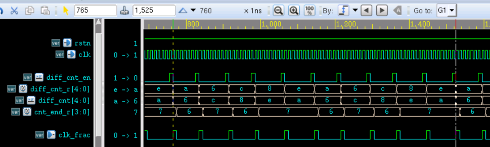
The simulation results are as follows.
Division summary
Even frequency division can achieve 50% duty cycle clock division without using the clock's double-edge logic, making it the most ideal frequency division condition.
For odd frequency division, if a 50% duty cycle divided clock is required, the clock's double-edge logic must be used. If duty cycle is not required, the implementation method is similar to even frequency division.
Half-integer frequency division is a special type of fractional frequency division and can be designed using double-edge logic. When combining two double-edge clock signals into a final output clock through certain logic, it is recommended not to use selection logic. This is because glitches are prone to occur and the circuit will also introduce additional uncertainty. For example, the following description is not recommended.
: clk_adjust_r ;
The basic idea of fractional frequency division is that the average frequency of the output clock over a period of time meets the division requirement. However, considering phase jitter, it is also necessary to average the division logic where the division coefficient changes.
Source code download for this chapter
Download